One of the most common issues I come across when dealing with RS-232 connections in AV is when the transmit and receive connections are the wrong way around (see my expanded article for more details on RS-232).
Here’s a few ways I have found to help get these correct, roughly in the order I would try them.
Labelling/Documentation
It seems obvious, but worth checking anyway. See if the devices themselves have any labelling or documentation to help with the connection.
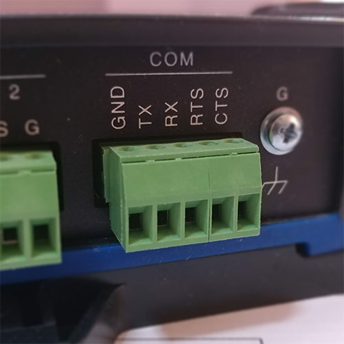
Phoenix connectors usually have ground (G or GND), transmit (Tx) and receive (Rx) labelled. If both sides have this labelling, then connecting the Tx from one to the Rx of the other is usually a good start.
DE-9 connectors are a little bit trickier. It’s worth checking the manual for these; sometimes they have either the pinout specified, or a diagram showing a connection to a computer. A control system can be treated the same as a computer in this instance.
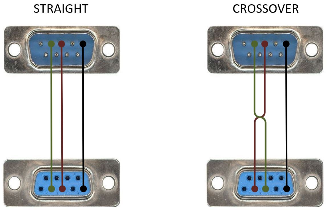
Failing that, a general rule of thumb is that if the connection genders are different at each end, then it’s a straight through cable (pin 2 to 2, pin 3 to 3). If they are the same gender then it could be a crossover (pin 2 to 3, pin 3 to 2). There are a lot of exceptions to this though so I’d probably check it by other means (below) before terminating.
Voltage – Multimeter
The vast majority of RS-232 ports will have a voltage present between the Tx pin and the ground. This is normally between -5 to -15V, even when there is no communication. The Rx pin will normally be floating or held down to about 0V between it and ground.
We can use this to our advantage… First make sure the device(s) are powered. Use a multi-meter to find the pin on each device that has voltage; this would be the Tx pin. Double check that the other pin doesn’t have voltage; this would be the Rx pin. Then connect the Tx pin on one device to the Rx pin on the other, and vice versa.
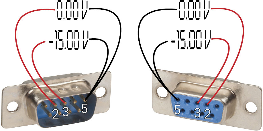
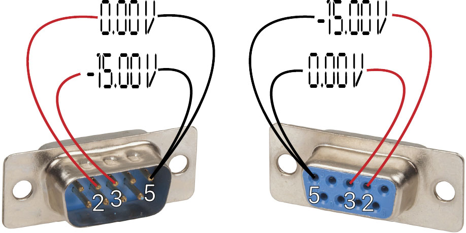
This way we don’t need to know which device is what type. The only time I have seen this fail is if the device doesn’t produce voltage on its Tx pin at rest, but this is pretty rare. One example in recent memory would a Sharp PN-LE901 LCD screen.
By checking the voltage on both sides, we can also confirm that the connection both ways should be good.
If you are dealing with a female DE-9 connector, an easy way of getting to the pins is to temporarily attach a solder cup type male connector, and then probe the back of that.
Voltage – Custom Tester
In the same vein, there are devices that give a visual indication of voltage on the pins by using LEDs, like this:
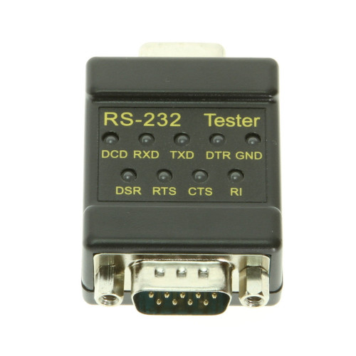
It uses the voltage on the pins to light the LEDs, and shows you which pins are active. These are most useful for DE-9 terminations; if you need to adapt one to Phoenix, you may as well just pull out the multi-meter to check the voltage directly.
I have made a few variations myself based on this. An example schematic of one is:
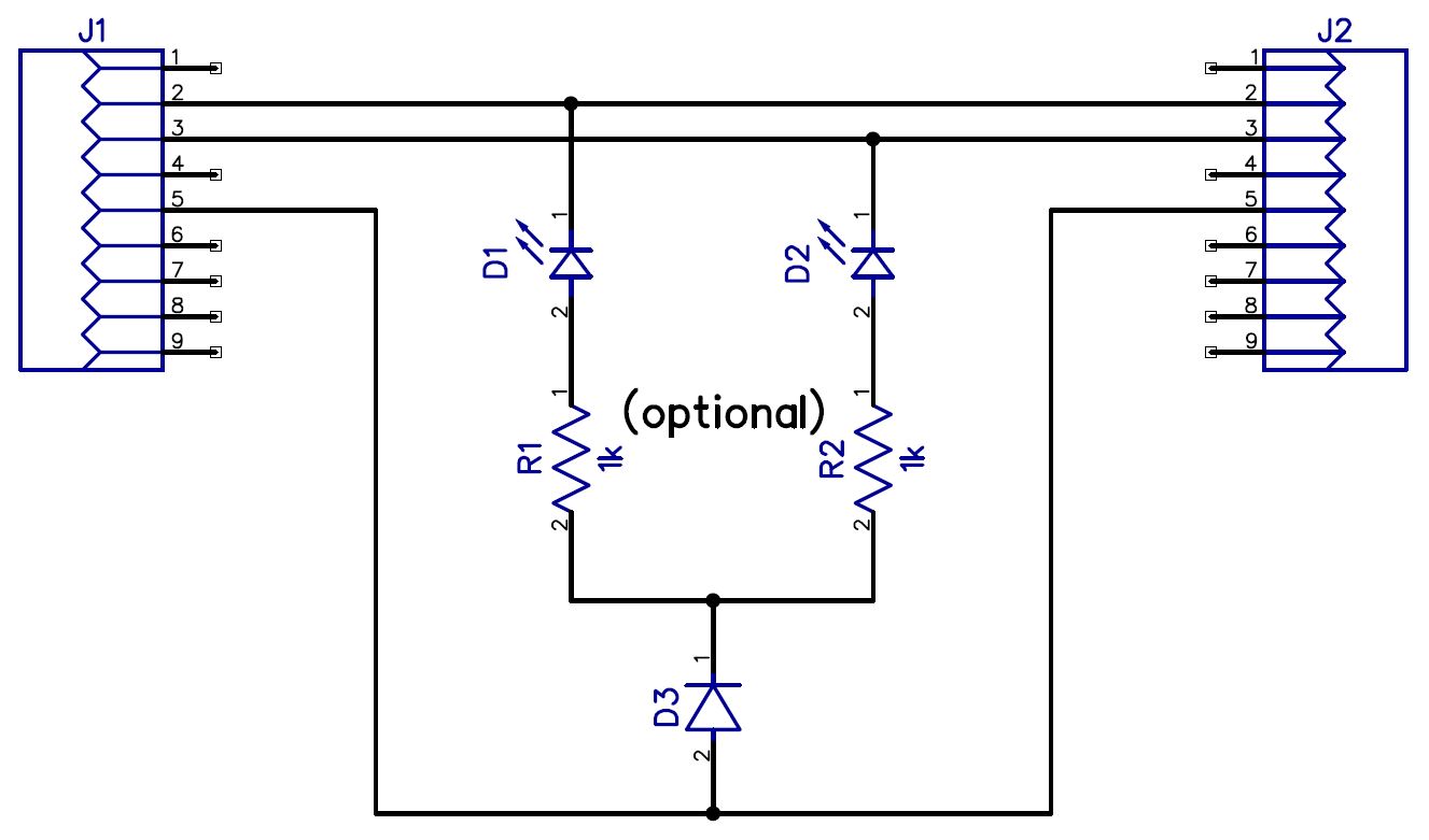
Connecting one side shows you which pin is the Tx. When placed inline with a complete connection, if both LEDs light then the connection should be good.
The resistors are optional because RS-232 ports are generally current-limited to a level that’s safe for LEDs. The shown value of 1k would give a result of ~13mA. D3 is probably optional as well; I connect one (the type doesn’t really matter) in just to protect the LEDs from the reversed voltage if there is traffic on the pin.
Communications
A laptop or a control system (or both!) can be used to help confirm the connection once it’s done.
You can use the debugging capabilities of the control system, but I commonly connect my laptop in place of the control system instead. This makes it easier to send/receive data to the device to test both physical connection and the communication properties (baud rate, protocol, etc). Also the debugging capabilities of the control system vary (e.g. with Extron GCP it’s read-only), and often the control system already needs code loaded to it to access the port at all. For lower level testing like this using my laptop I usual work with RealTerm as it gives easy access to serial port settings and how the data is displayed.
To try and test the communication, if you know the protocol, great; send something from that and see if you get a response. Otherwise, try enter, ‘?’, ‘help’, and similar. Failing that, a reboot of the device might prompt it to send some serial data.
If things still aren’t working as expected, you can also put the laptop in place of the controlled device. This involves knowing which way the termination needs to be so that you can cross it over as needed. It does mean though that you can check that the device would be receiving the expected commands and also that the communication path back to the control system works. This is more to test the programming than anything but can be handy to pick up a termination errors as well (like only transmit or receive connected).
