Despite its age (introduced in 1960!), RS-232 is still relatively common in the AV world. It’s simple, dedicated and reliable which makes it pretty effective for lower speed communication (do you really need 100-1000Mb/s to tell a screen to power on?). It is being slowly replaced with Ethernet communications which has its own advantages (e.g. standardised cable/connector, more functionality/manageability, higher speed if needed).
Until it does fade away, we still need to know how to work with it.
Signals and Devices
One of the aspects of RS-232 that keeps it simple is that it’s a serial interface. At it’s minimum, it needs 2 wires for one-way communication, or 3 wires for two-way. These are:
- Ground/Common
- Transmit Data (TxD)
- Receive Data (RxD)
There are other signals available, but these are rarely used in practice with AV equipment. The only thing I’ve seen used beyond the above has been hardware flow control (on a ClearOne DSP I think?), but even that was optional.
The actual definition of the TxD and RxD signals can be ambiguous; the manufacturers often don’t follow the official way of labelling this. To understand the official way we need to take a step back…
Device Definition
The RS-232 interface isn’t symmetrical; there something of a master/slave thing going on. The master is the Data Terminal Equipment (DTE), and the slave is the Data Communication/Circuit-terminating Equipment (DCE). In the classic case of a PC and modem, the PC is the DTE and the modem is the DCE. In the AV world, the control system is usually the DTE and the other equipment is… well… up to the manufacturer.
Signal Definition – Official
The TxD and RxD signals described above are both from the perspective of the DTE. This is regardless of which end you referring to. So the TxD pin on the DTE connects to the TxD pin on the DCE (and RxD to RxD). That’s right; the DCE receives data on its TxD pin, and sends data back on its RxD pin.
Signal Definition – Reality
That’s where the confusion starts: The manufacturer usually doesn’t specify if their device is a DTE or DCE. They also don’t usually specify if the TxD pin is referring to where the data is received in the DCE (official definition) or if it means where the data is transmitted from the DCE (which is actually the RxD pin). The best you can usually get is the pinouts, either directly or for a cable designed to connect the device to a computer.
In practice, most people refer to the pin sending data as the transmit pin, regardless of the end (so the transmit pin always goes to the receive pin on the other device). It’s more intuitive and practical when figuring out the connections, especially when you don’t know which is DTE vs DCE.
Electrical
The voltages used for Rs-232 are generally +/- 5-15V relative to ground. Between +/-1.5V or so is undefined (it depends on the receiver circuitry). Negative voltage (-5 to -15) is a logical 1/true, whereas positive voltage (+5 to +15) is a logical 0/false. This voltage is only generated on the pin that sends data on each side (this comes in handy for figuring out connections), and is current limited (about 10mA is normal).
A driving pin (sending data) will sit at negative voltage at rest (a logical 1), whereas a driven pin (receiving data) will be floating (often sitting at 0V).
Settings
Another aspect of the signal are the communication settings. These are the baud rate, number of data and stop bits, presence and type of parity bit, and flow control. These are often fixed by the equipment manufacturer (and hopefully documented) but can sometimes be adjusted.
The baud rate (number of signal units per second) is the most commonly adjusted, and is usually set to one of a number of standard rates such as 9,600 (most common that I’ve seen), 19,200, 38,400 and 115,200. Most of the time you aren’t transferring much information so a low baud rate is fine, but a higher rate could be useful with larger amounts of data, such as searching a VC codec phonebook, or ramping a volume slider in a DSP.
The other settings aren’t commonly changed from no parity, 8 data bits, 1 stop bit, and no flow control. A notable exception here is for Sony projectors; often they use even parity.
Connectors
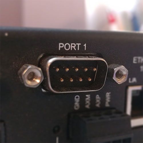
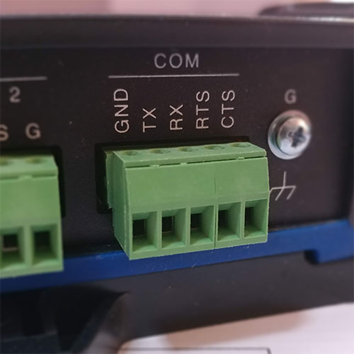
The two most common connectors I see around for RS-232 are DE-9 (D-Subminiature, ‘E’ size, 9 pins) and Phoenix/euroblock pluggable terminal blocks: RS-232 DE-9M connector


I’ve also seen it on 3.5mm (1/8″) TRS, mini-DIN and 8P8C modular (RJ45) connectors.
Phoenix/euroblock
The Phoenix connectors are generally easy enough to handle. They are good for custom cabling as they are easy to terminate, test and fix. Pre-terminated cables are rare though.
Figuring out the pinout is usually straightforward; it’s often printed on the equipment itself. The challenge is usually if the other end is a different connector, or figuring out the labelling convention used by the manufacturer (as above in Signals and Devices – Reality). The good thing is that they are easy to check with a multimeter (the screw tops are usually connected to the pin) and re-terminate if it’s not correct straight away. A good starting point is the Tx wired to the other device’s Rx and vice versa, and the grounds connected together.
DE-9
Sometimes (incorrectly) called a DB-9, this is more common on older equipment but is still around on some new gear. They are usually soldered or crimped, so a little bit more hassle to terminate but still quite easy.
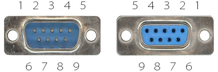
Generally the only pins you need to worry about are 2, 3 and 5 (Receive, Transmit and Ground respectively if it’s a DTE). The gender of the connector isn’t always consistent, but conventionally DTE/master devices (like a control system or computer) uses male connectors, while DCE/slave (like a screen or modem) uses female. This is why premade straight through cables are usually male to female, and crossovers are female to female. The pinout numbering is shown here:

If you are lucky the connector has the pin numbers embossed on the plastic next to each pin.
